hubbatech
Projects,
articles and links to information that may interest Radio Amateurs and
Electronics enthusiasts
.com.au
|
hubbatech
|
Projects,
articles and links to information that may interest Radio Amateurs and
Electronics enthusiasts
|
|
.com.au |
|---|
 |
|
In Australia, it is common for paging systems to transmit at frequencies just above 148 MHz. The Australian 2 metre amateur band is between 144 and 148 MHz which means that the very strong pager transmitters are capable of interfering with communications within our amateur band. Sometimes it can be the problem of the transmitter but more likely it is the receiving equipment which these days is designed to be broadband and so cannot tune out the unwanted signals. The best solution to this "intermodulation distortion" problem is some sort of filter at the front end of the receiver. Unfortunately this can not always help if you have a multi band radio as the filter may work too well. Anyway have a listen around 148 149MHz and you will hear what I am talking about. The number of members of our club who suffer from this interference at home is small and luckily I am not one of them. However I know of at least two of our members who were driven crazy by this and wanted to do something about it. Usually the interference gets into your receiver by intermodulation distortion ( look it up as this article is about the cure not the cause). Several methods can be employed to prevent the interfering signals from reaching your receiver. In similar articles, several filters have been described that would help with the problem but were not going to help the two amateurs that I know of. As I mentioned before, I do not suffer from the problem at home and I am not going to look at a cure for mobile operation but as I am lucky enough to have the equipment to test and tune this type of filter, I thought it would be interesting to take a look at building possibly a better filter than those previously described. To start with, I spent many hours trawling the internet looking for other peoples ideas and aside from a full blown cavity filter (or two), the best I found was the Helical filter. The features of the Helical filter are that they are small (relative to a full blown cavity filter) and very effective for their size. The helical coil (helix) is cut to be a roughly a quarter wavelength at the notch frequency. These filters can be cheap, but throw more money at it and it is bound to work better. Anyone can make one. Helical filters can be designed to be High Pass, Low Pass, Band Pass or Band Reject. However the criteria I was looking for are:
· Minimize or eliminate the problem interference with minimum insertion loss (the amount of loss of the signal that we want to hear).
· Keep the cost reasonable.
· Make it suitable for transmit as well as receive without bypass circuitry (if possible).
· Keep it small enough to fit on or under the operating bench without having to strengthen the bench to support it.
· Use readily available materials.
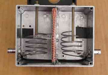
The Band Reject (or Notch) filter was the way to go as Band Pass filters tend to have a higher insertion loss and trying to get sharp (steep sided) cut off frequencies with a Low pass filter is not easily obtainable. Description: The Helical Filter uses a resonant circuit formed by the inductance of a coil of wire called the Helix and capacitance formed by a metal screen surrounding the coil of wire; together which, at the tuned frequency, will perform the filtering. All my attempts were variations of designs found elsewhere so I make no claim to originality. Version 1: Although this filter worked, I was not really happy with its performance so I set about making Version 2. This newer version used more of my gained knowledge and some formulae that applied to Helical Filters. I even found a program that will do some calculations for you (called of all things Helical). Figure 1 is a picture of my first attempt at a Helical Notch Filter (Version 1). It comprised two helical resonators and fine tuning was achieved by the capacitance added by the brass screws seen inserted at the top of the die cast box. The original design used piston type trimmer capacitors but I eliminated these in favour of the brass screw rods which have very low loss and therefore should create a higher Q for the filter. By the way I did try the trimmer capacitors but was not happy with the fine adjustments so that is why I went to the brass screws instead. I managed to tune the helicals to a slightly higher than required frequency without the brass screws by stretching and compressing the helix coils and pulling them down to final frequency with the screws. I later put a small disc on the end of each screw which was more effective.
Version 1.
Several other versions of this type of filter were found on websites but they were tuning the helix with variable capacitors. I found it easier to use the brass tuning rods shown in this picture.
The above filter gave me approximately 20dB of attenuation which was ok but could or should have been better. Each half of the filter gave 10dB of attenuation. The bandwidth of the notch was very narrow which I was happy with and the insertion loss at 2m was about 1dB. Although not terrifically rugged, this filter would work at a pinch. The impedance matching at 50 Ohms was acceptable for transmitting purposes from 145 147.5MHz. Also the die cast lid could not be installed due to the detuning caused so a piece of PCB was cut to size instead.. The coils perhaps could have been mounted vertically in an enclosure; then the lid would not have had such an affect. Note that the helix coils are floating (not connected) at the hot (top) end. When tested in series with a receiver at one of our worst sites, the receiver became usable again however I was hoping for something better.
Version 2:
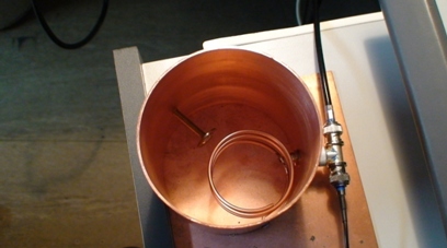
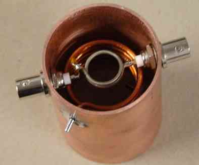
Well they say that bigger is better and it is the same for filters. I took several other designs, disseminated them and started to build what should be a much improved filter. This time I had a plan, and that was to build the helix using copper capillary tube 3mm in diameter, and the outer screen was to be copper plumbing pipe 100mm in diameter. The capillary tubing should give the coil some rigidity. I was going to build and test the filter, then pull it apart, silver plate the helix and interior of the pipe, then retest it to see how much difference the plating made. This is because silver has the best RF conductivity, and should increase the Q and the attenuation at the notch frequency and less attenuation at the desired frequencies (insertion loss). I managed to obtain the 100mm pipe easily but the helix tubing would have to wait for an EBAY delivery. The 3mm capillary tubing arrived just prior to my leaving for a trip overseas (well deserved if you ask me) but I managed to do a few tests before going. The photo below shows the Version 2 filter.
Version 2.
A single helix with the tapped connection into a "T" BNC connector with tuning performed by the small disc soldered onto the end of a long screw.
Notice that there is only one connection to the filter and that is via a BNC socket. The idea is to connect a T piece BNC adapter with the antenna connected to one side and the transceiver to the other side of the adapter. I wound the coil (helix) longer than required, as you would, and then proceeded to cut and stretch / compress it until the frequency came to just a bit higher than required. There is a combination of helix length versus number of turns that gives a sharper notch. A brass tuning screw similar to what was tried in Version 1 was installed for fine tuning. I did not want to add too much capacitance using the screw as this could affect the Q so I tried to set the self resonant frequency within +100kHz of the desired frequency (in my case 148.700MHz) which was between the two strongest pager transmitters in the southern Melbourne suburb of Keysborough. Hopefully the attenuation notch would be wide enough to kill off some of both of these frequencies. I was quite impressed by the results as I could get 30dB attenuation at the centre of the notch with a bandwidth that gave me about 25dB of attenuation at each of the two pager frequencies. The next concern was what was the insertion loss and impedance matching going to be like in the 2m band. The insertion loss was found to be about 1dB but is not easily measured on the test gear used. In the case that I was working on, this particular amateur really only wanted to use 145 146MHz region of 2 metres which made it slightly easier to obtain a reasonable SWR at 50 Ohm that far away from the notch frequency. The location of the tapping point for the BNC connector on the helix dictated where the best match would be without really affecting the notch frequency. A good match was achieved at close to 146MHz with the notch frequency remaining at 148.700MHz. Unfortunately I also discovered that the filter presented a deep notch in the 70cm Band at almost the third harmonic, which meant that the filter could not be used on a multi band transceiver unless some form of bypass switching was utilised for transmitting.
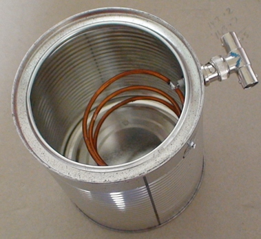
In the meantime I was contemplating yet another design but needed another amateurs help in obtaining some more copper pipe. While waiting for said pipe, I went back to Version 1 and retested at 70cm. I found that this filter did not exhibit the harmonic properties of Version 2 and would work on a multi band rig for receive and transmit. I also set about collecting parts to build a relay control to bypass in transmit mode while waiting to start on Version 3. I found a 100mm diameter coffee can and quickly built another model of Version 2 as I wanted to know how good the filter would be with a rough and ready approach. The filter took all of 15 minutes to build and exhibited pretty much the same results as the other model built in the copper pipe instead of this extremely thin tin can. The attenuation was about 25dB at the centre of the notch which was not bad for a quickie.
Version 2A.
A "quickie" coffee can version of number 2.
Version 3:
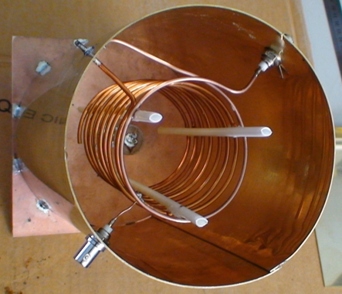
Of course not being happy with either of the first two designs (or the coffee can), I started again. This time I found a design similar to Version 2 but on a smaller scale; in a 75mm length of 50mm diameter copper pipe. The helix was built along similar lines as before but instead of tapping the coil at some point close to the earthy end, a coupling link was used. This was an easy build, taking about an hour once I had collected the parts required. Notice also that due to the coupling link, there are now two BNC connectors which I later found useful. By now I had run out of the capillary tube for coil winding so I dismantled a very high current transformer to use the secondary winding wire. This was great as I had now found a seemingly endless supply of 3mm diameter soft copper wire. I could experiment as much as I wanted. This filter showed an extremely low SWR across the 2m band with an insertion loss hardly measurable also. The notch was tuned for 148.7MHz or close to because I did not install the usual brass screw with capacitor plate on the end for fine tuning. Instead I stretched and compressed the helix to get it on frequency. This wasn't as hard as I thought it would be. However if I put end caps on the filter I would have to use something to do the fine tuning so that would come later.
Version 3.
This was the most successful of those that I built.
The attenuation at the notch frequency measured 15dB which was somewhat less than Version 2. I experimented with the coupling link coil but did not do any better than this figure. Note that the construction of the coupling link included a series capacitor (15pF) to tune it to work at 144 - 148MHz. Hence of course this filter would be no good at 70cm for transmitting through. This version of the filter seemed to give the best overall performance, taking into account size, insertion loss, attenuation, and receive problems at 70cm. I also experimented with the coupling link trying one with 2.5 turns instead of the 1.5 as shown here. I also decreased the value of the capacitor from 15pF to 5pF. The results were great for attenuation as this was now 25dB but the SWR curve was not great, making it unsuitable for transmitting through. However if one was going to use a bypass circuit for transmitting anyway, the increased coupling link would be an advantage if more attenuation was required. As I was beginning to think my time was up for filters and it was time to move on to other projects, I made a change again to the coupling circuit. This time I kept the 1.5 turn coupling coil but put a 10pF capacitor in series with it and mounted it just inside the bottom loop of the helix coil instead of outside of the helix. This achieved better coupling (20dB+) and the SWR curve was still acceptable from 145 to 147.5MHz. I have built two of these and tried to keep them identical but achieved slightly different results between them. Anyway they can be used in series to give 40dB+ of attenuation and still maintain a good SWR over 2m.
Version 3.
filter complete with end caps and screw tuning adjusters.
I took the filters to one victim's (read as "amateur with pager interference") shack and found that he was suffering more interference than the filters could attenuate so I took them away again. Upon trying them at a second victims shack, the problem disappeared immediately with only one of the filters in line. We determined that this amateur was suffering intermod. from a mixed source of more than two frequencies; one of which was a pager and another, a commercial two way transmitter. It was going to take some more work to help amateur number 1. I left the two cans with amateur number 2 who gave one to yet another sufferer who immediately wanted to know when I was going into production. He was pleased that once again he could use 2m. I could not find it in my heart to rip the filters away from these guys who were now enjoying pager free 2 metre operation but as I needed to work on amateur number 1 still, I broke the news and retrieved the cans in the hope of coming up with yet a better solution. After further testing I gave the "cans" back to a couple of very happy amateurs. Read on and you will find out what I did for amateur number 1.
The equipment used for tuning the filters included an IFR1200S with Spectrum Analyser and Tracking Generator plus a 50 Ohm Return Loss Bridge for checking the impedance matching (SWR). Oh and by the way, I never got around to silver plating any of these designs. Maybe another time as I had spent quite a lot of time and money on filters for the time being.
References: Various Internet sites too numerous to mention
RSGB Handbook
ARRL Handbook
ARRL Antenna Handbook
CQ Magazine June 1997
Conclusions:
The lessons learned :
Read a lot before starting to build.
Copper absorbs a lot of heat. (There is another story behind this comment but that will keep for another time)
Helical Filters work extremely well but the dimensions need to be right to obtain the best shaped notch or pass.
There are rules to adhere to.
They are only meant to work on one band.
Oh! and as for amateur number 1, I finished the Version 2 filter, set up a coaxial relay to bypass the filter in transmit mode using an RF sensing switching circuit and connected it all to his dual band (2m / 70cm) radio for which he is very grateful. He now enjoys using 2m again. As for me, I packed up all the leftover bits and found another project to work on.
Addendum: Since building the filters described above, I had the need to build a 6 metre band pass filter for our repeater which is receiving some unknown type of interference - probably intermodulation. I have included the report on this filter as an extra although it has nothing to do with pager interference. Someone may be interested in the results. The design for this filter although following the standard pattern for helical filters was described by Sam KT4QW. Although his website did not show all the details, he was gracious enough to respond to my email with the extra information that I required to build it. His design worked first up and we tried it on our 6m repeater which has a 6 notch duplexer already. Unfortunately the extra filter did not cure our problem but I learned some more in the process of building this band pass filter.
The 6 metre Band Pass filter
Naturally this filter is much larger than the 2m versions with the diameter of the can being 140mm. The height is 200mm. This is the view from the cold end of the filter before fitting of the bottom cover. At the top of the filter (far end) the fine tuning disc can be seen. This gave about 1MHz of variation which should be plenty. As the helix was quite large, it was physically very unstable hence the plastic tubing which was glued to the windings for rigidity. The 1.25 turn coupling coil is seen at the near end or cold end of the helix. SWR at the bandpass frequency was 1.3:1 and the insertion loss was hardly measurable however on real tests, the incoming signal did lose some strength. This is unfortunately a trait of bandpass filters. Also unfortunately the interference on our 6m repeater was not fixed by the insertion of this bandpass filter so it was removed, but it was another good learning curve.
TOP