hubbatech
Projects,
articles and links to information that may interest Radio Amateurs and
Electronics enthusiasts
.com.au
|
hubbatech
|
Projects,
articles and links to information that may interest Radio Amateurs and
Electronics enthusiasts
|
|
.com.au |
|---|
 |
Story of a Repeater Controller.In 2009 it was decided that our Club's 6 metre repeater was in need of a rebuild. The existing equipment had given excellent service for over 20 years but improvements in technology meant that the aging Motorola 6802 processor would not be adequate for what we had in mind. The original project was designed and built as a tertiary school project which I was unhappily given only a reasonable score as the teacher thought it would never be used. I wish he was around to see how long it survived. Maybe he would remark it somewhat higher. |
So began the story of the upgrade of VK3RDD repeater at Cockatoo - an outer eastern suburb of Melbourne, Australia.
The project was a collaboration between another amateur and myself that would take two years to complete in our spare time. The project grew from just the controller to the whole repeater including transmitter, receiver and the cabinet in which it lived.
The old VK3RDD was pulled from service in March 2011 so that any reusable parts could be recovered and interfaced with the new device. Only three items were able to be reused; the Power Supply (which had a modification built into it to allow the processor to monitor power failures), the PA Stage and the Cavities (Duplexer) which we discovered after sending off to the manufacturer for retuning were still in spec.
The Controller:
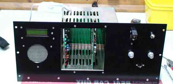
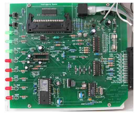
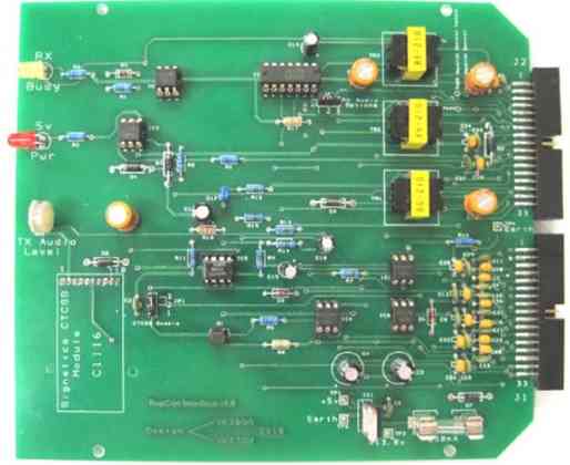
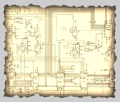
Consists of two PCBs; the CPU board which has an AVR microcontroller surrounded by support circuitry for connecting to the second PCB which is an interface board utilizing opto isolator ICs to prevent any destructive voltages feeding back into the CPU board. The CPU board has an audio recording IC which holds all of the voice recorded messages played by the repeater including the ident, signal report and error messages. A hardware watchdog circuit will reset the CPU if it sees that processing has stopped. DTMF decoding for remote controlling of the Controller is done on this board and a separate AVR processor on the LCD display communicates directly with the main processor to update information on the LCD. Several pages of information can be accessed to assist with diagnosis of faults if they occur. The Interface board has a CTCSS module which can be remotely activated / deactivated. It has audio mixing and switching circuitry and controls the PTT, squelch, signal strength voltages and RF power level measurement circuits. Both of the above boards plug into a backplane which also supplies power and interface connections to the radios and measuring sensors etc. All modules of the Controller are mounted on the Control Panel shelf along with local controls and switches. A local microphone is plugged into a DIN socket on this panel.
The Transmitter:
This is an AWA RT85 late (well later) version with a 2716 EPROM used to set the frequency of operation. Small modifications have been performed to the Transmitter such as setting it into the LOW power position so that only 2 watts is fed into the outboard PA stage. For this reason, the transmitter and receiver radios cannot simply be swapped unless the output of the transmitter is removed from the outboard PA stage and fed directly into the duplexer TX port. Swapping the radios will also prevent the signal strength measurement from working.
The Receiver:
This is also an RT85 late version with a 2716 EPROM. Small modifications have been performed to the Receiver such as connecting to the RF stages to measure the strength of the incoming signal.
TX Switching Unit:
This unit contains a relay and a manual override switch to control DC power to the Transmitter. It is mounted on the rear of the front panel of the TXD / RX shelf. The relay is normally activated by the Controller but in the event of a fault, the power to the Transmitter can be switched off automatically or remotely thereby preventing damage to the outboard PA stage. A front panel switch can override this setting.
Above and below is the Controller comprising the two main PCBs; the Processor board on the left and the Interface board on the right.
Following the two intense years of software writing and designing the hardware plus many days of exhaustive testing for both of us, we were ready to install the new equipment to site. In March 2010, the old repeater was decommissioned and work started on assembling the modules for the new one into a new larger cabinet with room for a backup battery and mini electrical switchboard. In June of that year, the repeater was put on air and needed very little tweaking to get things right. The audio was given the thumbs up as being clear and natural sounding and the door was closed on another project - or so we thought. Unfortunately the site was suffering from a receive interference issue which to this day has not been resolved due to a number of reasons none of which are under our control. Luckily having CTCSS designed in, it was a simple matter of enabling this and although the problem has not gone away, at least the repeater is usable.
The repeater has been in service again for over 12 months and although the interference issue has given us some grief, we are both extremely proud of our achievement. Both of us have moved on to other projects but still discuss this project at every opportunity. With any project of this size, documentation was a important point and much was written and collated as we went.
The User Guide can be viewed here.
Some features of the new controller are:
The ability for users to request a signal strength report.
LCD display for on site reporting.
Voice Ident when idle plus morse ident if occupied.
Remote control by administrators of many functions and settings. Auto shutdown under critical fault conditions.
Easily configured for different or new radio equipment.
Easily updated software. Modular construction for easy fault finding if required. Tamper alert, battery monitoring and mains power off alert.
On air voice messages for clear reporting of faults and status.